Multimode fibre optic communication systems, employing mode/mode group multiplexing, present challenges in accurately identifying numerous modes and mode groups for improved performance. In this study, we propose an intelligent identification model utilizing a fully convolutional neural network (CNN) to precisely identify multimode fibre modes and their clusters. The model is simulated and experimentally validated, considering noise influences on linear polarisation modes. Using a platform with OM2 multimode fibre and a multiplane optical conversion mode multiplexer, we capture optical field information for 10 modes and their corresponding mode groups. Extensive data are employed for training and validation, achieving a 100% recognition rate for all modes and mode groups in experiments. Notably, when employing a 44-photodetector array, an impressive 98.3% recognition efficiency is attained, showcasing the potential of deep learning in advancing multimode fibre optic communication systems.
The Internet of Things, cloud computing, online shopping, online games, and short movies have all developed quickly, ushering in an era of information explosion with ever demanding standards for information transmission speed and capacity. As the central node of information and communication networks, the short-distance optical interconnection system that data centres and supercomputing centres represent needs to significantly increase its transmission capacity [1]. Multi-dimensional optical signal multiplexing technology has thus been thoroughly researched and put to use in real-world settings. Time, frequency, polarisation, and phase of optical communications have all currently been used to their utmost potential. Nevertheless, these technologies are getting close to the fibre optic communication system’s capacity limit. The novel technology of space-division multiplexing (SDM) based on the spatial dimension of optical signals has been presented and thoroughly researched in order to further overcome the capacity bottleneck [2]. Space division multiplexing, which primarily uses core division multiplexing based on multi-core fibre (MCF), mode multiplexing (MDM), and mode group multiplexing (MGDM) based on few-mode fibre (FMF) or multi-mode fibre (MMF), uses the spatial dimension of transmission channels to transmit data information independently [3]. The 5 Tbit/s bi-directional LPM system for multimode fibre [4] is one of many high-capacity transmission systems based on line polarisation mode (LPM) multiplexing or mode group multiplexing that have recently been widely publicised. Mode (group) multiplexing systems therefore have a wide range of potential uses in the future. The main components needed for this kind of system are the mode multiplexer/demultiplexer [5], space division multiplexing fibre [6], and space division multiplexing optical amplifier [7]. Therefore, in these modern fibre optic communication systems, it is crucial to define certain modes that correlate to the associated mode demultiplexing [8]. A mode monitoring method with intelligent recognition of polarisation modes and mode groups of a multimode fibre line should be investigated to improve the transmission performance of the system and to improve the mode recognition characteristics of the mode multiplexing system and the flexibility of mode management.
The term “optical fibre couple transmission system” primarily refers to a range of passive special-purpose optical fibre devices that may be made to continuously couple and transmit a number of energy information and optical signal channels with dynamic power distribution [9]. One of the three novel varieties of coupled optical passive devices, it has the most scales and has been extensively used in the development of optical fibre system technology [10]. They’ve held a key and distinctive position in the field of systems. The majority of transmission devices are single-fiber devices, which fall into this category and are of the all-fiber type, according to the technical characteristics of optical fibre couples, which are generally accepted to have at least the following common performance characteristics [11]. The second is that optical signal multiplexer transmission and optical signal composite beam transmission take place primarily during the transmission of the optical field, and the transmission can be achieved directly using the mode couple method. The third is that it implies that the direct transmission of the optical signal wave must be able to have a specific direction [12].
The fibre optic broadband and communications market in China has developed quickly, thoroughly, and soundly as a result of the success and introduction of the fibre optic couple welding technology. As we approach the middle of this century, the single mode communication technology of optical fibre is gradually replacing the conventional multi mode technology in the optical fibre mobile communication network. Due to this, combined Application research and development of optical fibre single-mode communication and optical fibre couples has increased significantly in domestic academic circles [13].The FBT process Technology is used to process and manufacture fibre optic couple material items after several experiments and investigations over an extended period of time [14]. There are numerous important technological benefits, such as cheaper equipment operation and maintenance costs and good, mature all-fiber packaging technology. Although FBT technology can be developed and applied, we can currently essentially fully satisfy the functional and basic needs of businesses as a result of the expansion of the couple market [15]. However, Chinese businesses will need to rely on further advancements in technology and research if they are to maintain their absolute core competitiveness and absolute market advantages in the future, when industrial competition is expected to become more harsh and complex [16]. The technological bar has been raised and significant advances in research have been accomplished. Future ultra-large-scale integrated logic circuit FBT technology developed in my nation will swiftly transition to a dependable industrialization technology as well as gradually mature towards a different process technology that is comparable to one-time production and assembly of semiconductor chips. In the future, following one processing and assembly, as many as several, dozens, or even hundreds of integrated circuit products and core components can be created and packaged at once, together with the packaging [17]. A lot of integrated circuit goods can be created after processing and assembly if the products can be further divided and packaged [18, 19, 20].
Low-loss optical fibre technology, which serves as the foundation of this technology, first appeared in 1970.It is the first significant breakthrough technological advancement in the optics sector, offering the most cutting-edge and potent technological methods for the quick creation of new optical fibre systems [21]. Meanwhile, it has created a very strong research material foundation for the production and application of optical fibre pair goods on a big scale [22].
Dotty, Bis Bee, and others made the observation that the new optical fibre couple would be created utilising the fused optical fibre technique. Between two fused optical fibre bundles, it can effectively realise the full single-channel coupling connection and the full directional optical fibre transmission. This fibre fusion coupling technique also identifies a crucial path for the creation of a new generation of fibre couple apparatus.
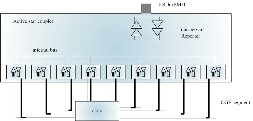
Hudson and Thieu developed the first star fibre pair, seen in Figure 1, in 1974 after proposing the concept of a star couple.This multi-port fibre star couple offers various benefits over the conventional T-shaped couple, including lower loss, better directive, more stability, and equivalent ports.A technical assurance for the integration and miniaturisation of optical fibre communication systems and optical fibre sensing systems is provided by the emergence of star couples [23].

This paper primarily proposes an intelligent identification model for modes and mode clusters in multimode optical fibres based on deep learning. It also introduces a fully CNN to simulate and experiment with line polarisation modes and their mode clusters under the influence of noise.
Linear polarisation modes, vector modes, and vortex optical modes are the principal mode multiplexing objects used in contemporary fibre optic communication systems. The linearly polarised mode LPmn, where m and n stand for the radial and angular coefficients required to describe a specific fibre mode, is one of the frequently used multiplexing modes. For linearly polarised mode multiplexing optical fibre communication systems, some of the mode groups and their corresponding merged modes (such as LP11a, LP11b modes, etc.) are currently depicted in Figure 2.

Due to the high intermode crosstalk caused by the numerous modes in multimode fiber-based linearly polarised mode/cluster multiplexing communication systems, the optical field intensities of the output modes are very variable. Mode rather than mode group multiplexing and mode group reception is typically used to reduce the received power fluctuation caused by mode crosstalk. This situation calls for precise matching and demultiplexing of the mode channels carrying the signals at the receiving end in order to optimise the transmission performance of the system. The mode identification method for multimode optical fibre communication systems is the process of identifying and demultiplexing the optical fibre mode channels utilised in the communication system by learning the optical field information gathered at the receiving end.
Currently, fibre optic communication systems have been extensively
explored and reported on using neural network-based optical performance
monitoring approaches. One of these hotspots in the investigation of
space division multiplexing optical fibre communication system
performance monitoring is the intelligent pattern recognition approach
[21, 24, 25]. This approach can
achieve good performance in pattern identification and monitoring by
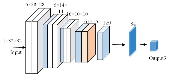
training on a lot of pattern data sets. Figure 2 illustrates a CNN
for the recognition of line polarisation modes and mode group optical
fields. One input layer, two convolutional layers, two maximum pooling
layers, two fully connected layers, and one output layer make up the CNN
model known as LeNet-5. Gradient descent training allows this multilayer
convolutional neural network to learn sophisticated high-dimensional
nonlinear mapping from a huge number of examples, making it an excellent
choice for image recognition. In this study, the relevant mode groups’
light field intensity distribution data are gathered using a
charge-coupled device (CCD) camera, and these data serve as the neural
network’s training and testing sets. The CCD camera has a resolution of
1280
The fundamental operation of this approach is as follows, as shown in Figure 3. Setting the parameters of the first convolutional layer C1, which primarily consists of 6 convolutional kernels of size 55, and then producing the 2828 size of feature maps after convolutional processing of the input data with a step of 1, are the first steps. In the largest pooling layer S2, non-overlapping maximum values are sampled in the input domain of size 2 in the largest pooling layer S2.
In the maximum pooling layer S2, non-overlapping maximum value
sampling is performed on the input data of 28

First, the LeNet-5 convolutional neural network is used to conduct a
validation analysis of the noisy linear polarisation mode optical field.
The field distribution of the core and cladding can be described as Eq.
1 and 2 in the column coordinate system:
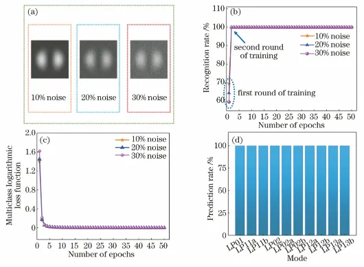
The Scipy package in Python’s least-squares function is used to calculate the U and W values of each mode, and the light field distribution of each linearly polarised mode is simulated. The first step is to simulate the fibre modes numerically. The key parameters are the numerical aperture (NA) of 0.08, the wavelength of 1550 nm, and the core diameter of 62.5 m. Ten linearly polarised modes (LP01, LP11a/b, LP21a/b, LP02, LP12a/b, and LP31a/b) are chosen for the noise analysis and are depicted in Figure 3. In order to simulate the optical field identification of the fiber mode under the condition of using low-cost and low signal-to-noise-ratio CCDs, 10%, 20%, and 30% noise are used as the randomly distributed noise intensity values. Taking the LP11a mode as an example, the light field of the mode under different noise intensities is shown in Figure 4(a). The intelligent pattern recognition model uses 500 images as the training set and test set for each noise intensity, with 400 images serving as the training set. The model’s training iteration process is depicted in Figure 4(b). After the initial round of training, the recognition rate of the pattern light field is 70%, 65%, and 60%, respectively, depending on the noise intensity, meaning that the higher the noise intensity, the lower the recognition rate of training. However, after the second round of iterations, the recognition rate can reach 100%, and in the following training iterations, a stable 100% recognition rate can be realised. The essential alterations are depicted in Figure 4(c) and involve the use of a multiclass logarithmic loss function as the loss function for multiclassification training. The function eventually converges to zero over numerous training iterations. Additionally, 100 pattern light field maps with various noise distributions but the same noise intensity are submitted to category prediction following model training and validation. The results are displayed in Figure 4(d). The outcomes are displayed in Figure 4(d). The predicted outcomes demonstrate that this intelligent pattern recognition model’s recognition rate can reach 100% for each pattern, demonstrating the model’s efficacy.

The model is then trained with 20% noise intensity of the modal light field data to enable it to identify the mode groups that belong to various modes in order to explore the model’s capability to recognise mode groups. The 10 linearly polarised modes are divided into four groups: simple mode group 1 (LP01), mode group 2 (LP11a, LP11b), mode group 3 (LP21a, LP21b, LP02), and mode group 4 (LP12a, LP12b, LP31a, LP31b). The modes and their respective mode groups are depicted in Figure 1. 500, 1000, 1500, and 2000 light field images are utilised proportionally to train and test the recognition model, with 20% of the images in each group serving as the test set. This is done while taking into account the various sorts of modes in the various mode groups. The model’s recognition results are displayed in Figure 5, where it can be seen that after the third round of training, the recognition rate of the model achieves 100% steadily, and the multiclass logarithmic loss function quickly gets closer to zero. As a result, the simulation outcomes demonstrate that the intelligent identification model has a high recognition rate and very low loss for various modes, demonstrating that the model is capable of categorising various linear polarisation modes into mode groups.

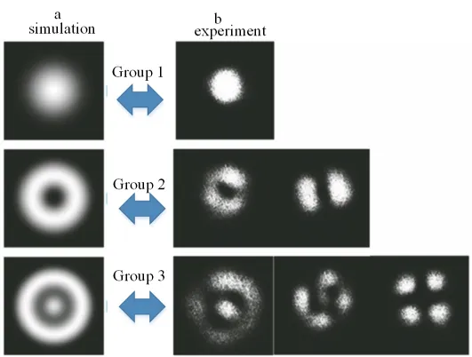
In a multimode fiber mode group multiplexing system, in order to avoid large mode crosstalk and dramatic received power fluctuations, in addition to selecting a mode of a mode group for multiplexing, a multimode detector is used at the receiving end to receive the superimposed optical field information of all modes in the mode group. Under the condition that the intensity of each simple linearly polarized mode within a mode group is equal, the simulated optical fields of different mode groups, such as mode group 1 (LP01), mode group 2 (LP11a, LP11b), and mode group 3 (LP21a, LP21b, and LP02), are shown in Figure [f6](a) after multimode stacking of OM2 multimode fiber output. It can be seen that there is a significant difference between the output light fields of different mode groups. In reality, however, external forces can readily disrupt the optical signal that is travelling in the OM2 multimode fibre, changing the output optical field as seen in Figure 6(b). The capability of mode group identification in real-world circumstances is provided by this shift in optical field information. The light field distribution of the swarms changes continuously as external force is applied to the multimode fibre of the swarm multiplexing system, and the obtained light field information is inputted into the neural net model for learning and training, which is able to simulate the capability and viability of the swarm identification under the real conditions.

In order to verify the recognition ability of the intelligent mode
group, an experimental system as shown in Figure 7 was set up. The
wavelength of the external cavity excitation is 1550 nm, which enters
the multiplanar optical mode multiplexer through single-mode optical
fiber, and the fundamental modes are converted into the corresponding
modes (LP01, LP11a, LP11b, LP21a, LP21b, and LP02), and the converted
linearly polarized modes are transmitted into the 10 m OM


Low-density photodetector arrays can be used as an alternative to obtain the multimode light field data, lowering the cost of the intelligent recognition model. In order to imitate the information gained by the low-density photodetector arrays, the received images of the multimode light field intensity distribution are rebuilt into 88, 66, and 44 resolution images. These images are then used for model training and recognition. Model training results are shown in Figure 7.
resolution of 8
resolution of 6
When the resolution is 6
The resolution of 4
At the same time as standard fibre optic technology is developing and advancing quickly. One by one, the byproducts of polarization-maintaining fibre optic couples have started to emerge. Polarization-maintaining fibre couples already have their own clear advantages in several areas when compared to other common fibre couples. As a result, it will be utilised more and more in the design and development of new complicated optical fibre communication application systems as well as in the disciplines of optical fibre sensing technology [26]. Additionally, it will be utilised as a better, more reliable, and high-performance polarization-maintaining fibre couple. The development of pertinent theoretical research and Application fields of polarization-maintaining optical fibre material Technology and the Application of particular industry products have over time become a hot topic in academia in other countries, and domestic research and development issues related to polarization-maintaining optical fibres and their Application devices will also follow [27]. It began to receive steadily greater attention from the academic communities of different nations. Due to the unique optical and polarization-maintaining properties of fiber-related products, they may be further widely used in many other important Application materials in the world.
Many crucial features of previous instruments are shared by the polarization-maintaining fiber-coupled device, such as the comparatively low extra power transmission loss and minimal polarisation phase crosstalk coefficient [28]. Additionally, it has the ability to automatically retain the linearly polarised spectrum created from the fibre transmission’s channel signal. In order to meet the accuracy and reliability requirements of its detection as well as various accuracy requirements, which are related to the performance requirements of the detection system, it has gradually evolved into a new type of fibre optic hydrophone coupling device and a new type of fibre optic gyro sensor. It has been thoroughly integrated and used in the construction of numerous military coherent communication sensor systems and numerous military interference communication sensor products as a system component and core component [12]. This new class of high-performance, polarization-maintaining optical fibre passive devices is significant and widely used. The national competent authorities have made significant investments in scientific research over the last few years in order to strongly support and create innovative, high-efficiency polarization-maintaining fibre couples for future applied research [16]. In order to actively join the ranks of the new high-performance polarization-maintaining fibre couple and its Application field of research experiments, it attracted a sizable number of high-level professional young scientific research and engineering experts. Chinese high-speed polarization-maintaining fibre couples and their application areas will undoubtedly continue to expand and develop quickly in the future, eventually becoming a common technology used by most people.In addition, as the final product in the polarization-maintaining fibre couple series, the single-mode polarisation fibre couple product provides significant optical performance advantages and successfully resolves the crosstalk of optical polarisation modes.
High-performance photogenic crystal fibre devices and its op to-coupled optical devices have recently attracted the attention of optical communication researchers both domestically and internationally.The aforementioned significant landmarks have been reached. The structure of high-performance photogenic crystal fibre and its couple type semiconductor device is divided into the three following major categories from the perspective of the research method of crystal optical structure design: fused cone type photogenic crystal fibre and its couple, side polished high performance photogenic crystal fibres and their couples, and dual or even larger multicoloured high performance photogenic crystal fibres and their couples. According to the research, the other most crucial and fundamental elements that make up the entire photogenic crystal fibre network structure must be provided for the photogenic crystal fibre technology to be successfully realised or be able to be used normally in various optical fibre and communication cable transmission medium system structure schemes. structural fibre components, where fibre couples should be the most fundamental and important optical fibre components. As a result, photogenic crystal fibre couples and their systems will have very promising future applications.
An intelligent mode/mode group identification method based on convolutional neural network is proposed, and its theoretical and experimental studies are carried out, in order to meet the performance improvement requirements of multimode fibre communication systems based on mode/mode group multiplexing. A multi-planar optical converter mode multiplexer and a common OM2 multimode fibre were used to set up a validation experiment for mode group identification, and the neural network was trained and validated by obtaining 3232 high-resolution optical field data of multimode mixing. This method can obtain a 100% mode group identification rate, according to the results of intelligent mode group identification. The image with a resolution of 3232 is then deconstructed into images with resolutions of 88, 66, and 44 to replicate the recognition capabilities of the low-density photo-detector array in order to lower the realisation cost of the recognition method. The final training recognition rates for the neural network can approach 100%, 100%, and 98.3%, respectively, after it has been trained on the low-resolution light field data. The experimental findings demonstrate that a sparse photodetector array can also achieve a high rate of mode group recognition. In essence, this study shows how convolutional neural networks can intelligently recognise fibre mode/mode clusters in simulation and experiment, which can offer technical support for multimode fibre communication system performance improvement and intelligent optical performance monitoring.
The experimental data used to support the findings of this study are available from the corresponding author upon request.
No funding is available for this research.
The authors declare no conflict of interests.
1970-2025 CP (Manitoba, Canada) unless otherwise stated.