
Three-dimensional (3D) braided composite material is near-netshape manufactured by the interweaving of fiber bundles with specific braiding rules, which has been an indispensable new material in many high-tech sectors [1-7]. At present, a large number of researches are mainly focused on three-dimensional braided composites from the aspects of braiding machinery, manufacturing technology, solid forming process and mechanical properties [8-16].
Nowadays, scholars usually conduct numerical simulation research on the mechanical properties of 3D braided composites by establishing a simplified model with finite element software [17-21]. There are mainly two kinds of numerical simulation methods based on the whole structure model of 3D braided composites. The first is multi-scale homogeneous analysis, i.e., homogenizing the heterogeneous fiber/resin material into the micro/meso/macro-structure model step by step. Then the established macro-scale homogenization model can be used to predict the elastic property constants of the whole material, so as to realize the numerical simulation of the material. The second method is multi-scale heterogeneous analysis, i.e., homogenizing the heterogeneous fiber/resin bundle into macro-scale fiber bundles model. Then the established macro-scale heterogeneous model can reflect the internal yarn network braiding structure of 3D braided composites truthfully.
For example, Zhai et al. [22,23] investigated the elastic behavior and failure strength of 3D braided composites under the representative unit cell scale and tow architecture scale. And the correlation between two scales was derived based on the continuum mechanics, homogenization method and the multiphase finite element method. Zhang et al. [24] presented a thermal-mechanical coupled constitutive model for the temperature rise and the coupling stress of the 3D braided composites based on the homogenization method under different impact compression conditions, i.e., temperatures and compressive loadings. Niu et al. [25] proposed the double-scale model for 3D four-directional braided C/SiC composites to predict its elastic properties. The model involved micro-scale fibers tows into consideration with the internal unit cell. Wan et al. [26] proposed a multi-scale structure model to analyze the damage behavior of 3D orthogonal woven composites subject to quasi-static and high strain rate compressions. The model included the micro/meso/macro-structure model for homogenizing the heterogeneous fiber/resin system into unit cells. Zhang et al. [27,28] established three distinct solid structure models of unit cell located in the interior, surface and corner regions of 3D braided composites for the deformation and stress distribution and the effects of the braiding angle and fiber volume fraction on the elastic constants. Zhang et al. [29,30] investigated the macro-mechanical properties of 3D braided composites with the fiber embedded matrix model related to the full-field fiber distribution. Lomov et al. [31] analyzed the meso-structure model of 3D braided composites by combining with the digital image processing, fabric permeability tensor calculation and ABAQUS finite element software. Li et al. [32] established the full-size mesoscopic geometrical model by using CATIA-V5-R20 software for analyzing the shear performance of 3D braided composites under impact compression. Pan et al. [33] used the above full-size finite element model to analyze the variation rules of mechanical properties of 3D braided basalt/epoxy composites at high strain rates under room and low temperature. Wang et al. [34-35] analyzed the thermal expansion behaviors and interfacial thermal stress of 3D braided carbon/epoxy composites in various temperature fields ranging from 100 ℃ to 140 ℃ with the above full-size finite element model. Wan et al. [36] proposed a computationally efficient multi-scale methodology for predicting the effective elastic properties and the failure strength of 3D braided composites from fiber/matrix scale to composite scale. And the results obtained from the whole structure heterogeneous composite model and the homogeneous composite model were compared, which provide an important guidance for evaluating the mechanical properties and selecting structural parameters for braided composites.
However, the above two kinds of numerical simulation methods have both advantages and disadvantages according to the analysis and classification of relevant references. For the multi-scale homogeneous model, it is easy to be built and needs low calculation cost, but cannot reflect the failure mechanism of the materials from the micro-scale aspect. For the multi-scale heterogeneous model, it is complex and difficult to be built, but can reflect the braided structure characteristics of 3D braided composites realistically. In addition, few researches are about the methods for establishing macro-scale simulation model and the numerical simulation of mechanical properties of 3D braided composites.
In this paper, a new method to establish the macro-scale simulation structure model of 3D five-directional braided composites is proposed by combing the computer software programming method and 3D modeling technology. The space trajectories of braided yarns and axial yarns are described by computer language according to 3D five-directional braiding process. Then the virtual simulation model is realized in the way of “point-line-solid”, and is correspond to the real braided structure. By using the macro-scale simulation model, the transverse impact compression characteristics, dynamic damage laws and failure mechanisms of 3D five-directional braided composites are systematically studied and verified by combing the experiment and numerical simulation. The research can provide a basis for the design of impact resistance properties of 3D braided composites.
Figure 1 illustrates the braiding schematic diagram of 3D five-directional braided composites. The preformed part is woven by adding axial stationary yarns on the basis of 3D four-step braiding technique. Each yarn is driven by a separate carrier in the braiding process. The carrier bound to the braiding yarn moves in accordance with the rules of four-step braiding process, but the one bound to the axial yarn does reciprocating motion at the step size of 1 between each row of its adjacent braided carriers. The braiding structure is stabilized by squeezing the adjacent yarns after one braiding cycle. Then, do reciprocating motion as described above. The 3D five-directional braided composite preform with rectangular cross-section shape can be obtained finally. It is found that the motion trajectories of braided yarns and axial yarns are different. In this paper, the space trajectories of braided yarns and axial yarns are described by computer language respectively.
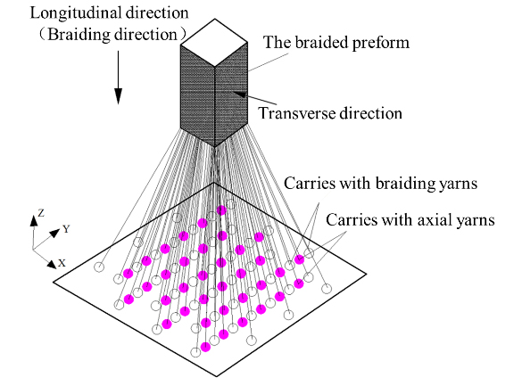
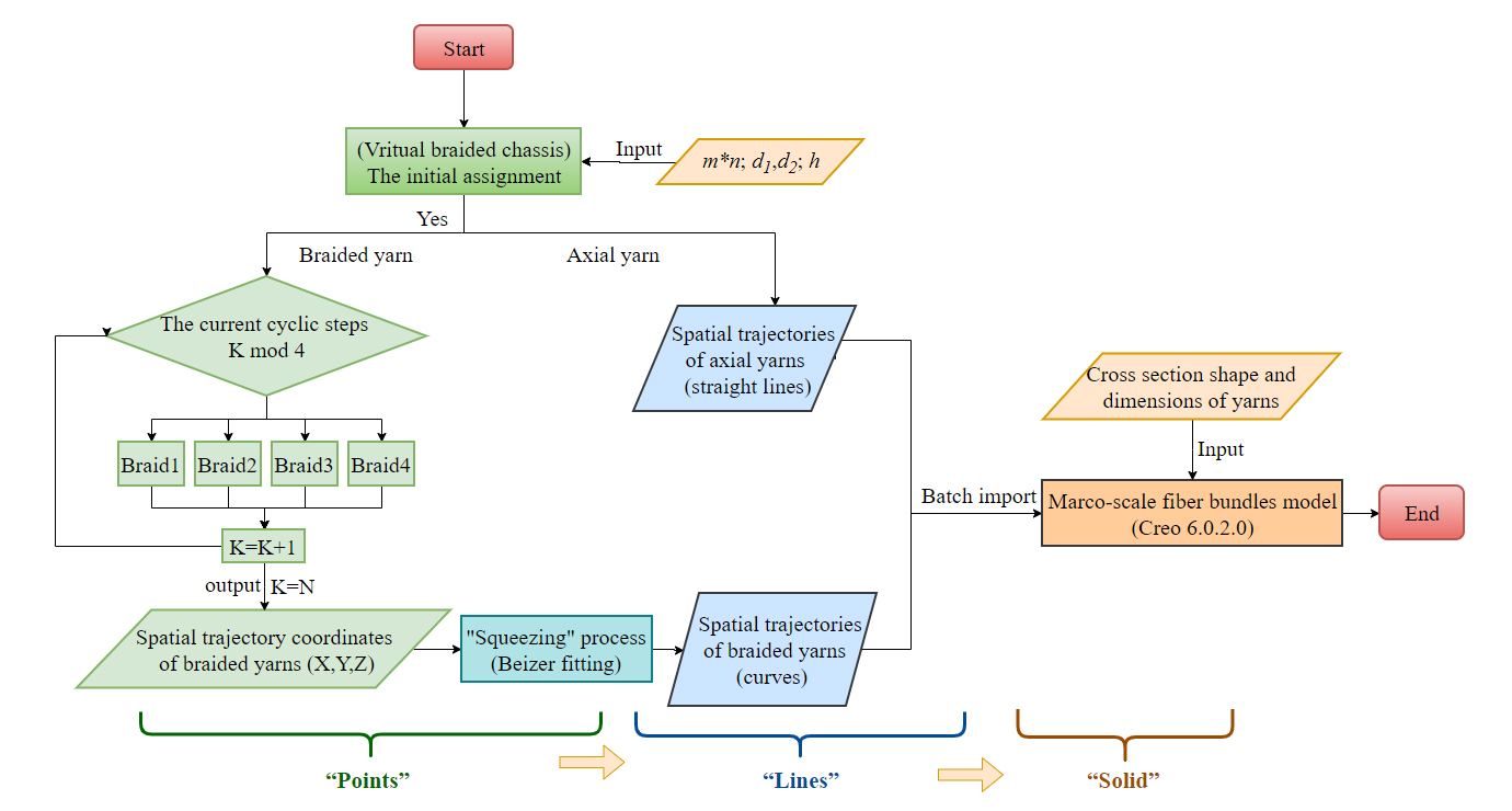
Figure 2 shows the flow diagram of computer simulation system of 3D five-directional braided composites. It takes MATLAB R2016A software as the computer programming development platform and Creo 6.0.2.0 software as the solid model simulation platform. The motion of braided yarns and axial yarns can be described by a series of algorithms in computer language to obtain the spatial trajectory of yarns. Thus, the spatial curve structure of yarns can be modeled in this way from “point” to “line”. The macro-scale fiber bundles model can be built in this way from “line” to “solid” by importing the cross-section shape and size of the yarn. Finally, the “point-line-solid” simulation modeling of 3D five-directional braided composite structure is proved to be correspond to the real braided structure approximately.
In this paper, the parameterized macro-scale modeling is very efficient. The parametric design variables required in the computer simulation of 3D five-directional braided composites mainly include the fabric arrangement, braiding angle \(\alpha\), the X– and Y-direction yarn spaces \({{d}_{1}}\) and \({{d}_{2}}\), the braiding pitch h and the cross-section shape and size of yarns. The specific methods are as follows:
The initial assignment of the spatial coordinates of each yarn on the virtual braided chassis, i.e., the initial arrangement of the yarn carrier;
The algorithm description of 3D four-steps braiding rules [37], i.e., the computer language programming of 3D four-steps braiding process;
Bézier function curve fitting the trajectories of braided yarns, i.e., the description of the “squeezing” process;
The algorithm description of the axial yarns motion, i.e., m×n straight lines approximately along the Z-direction on the braided chassis.
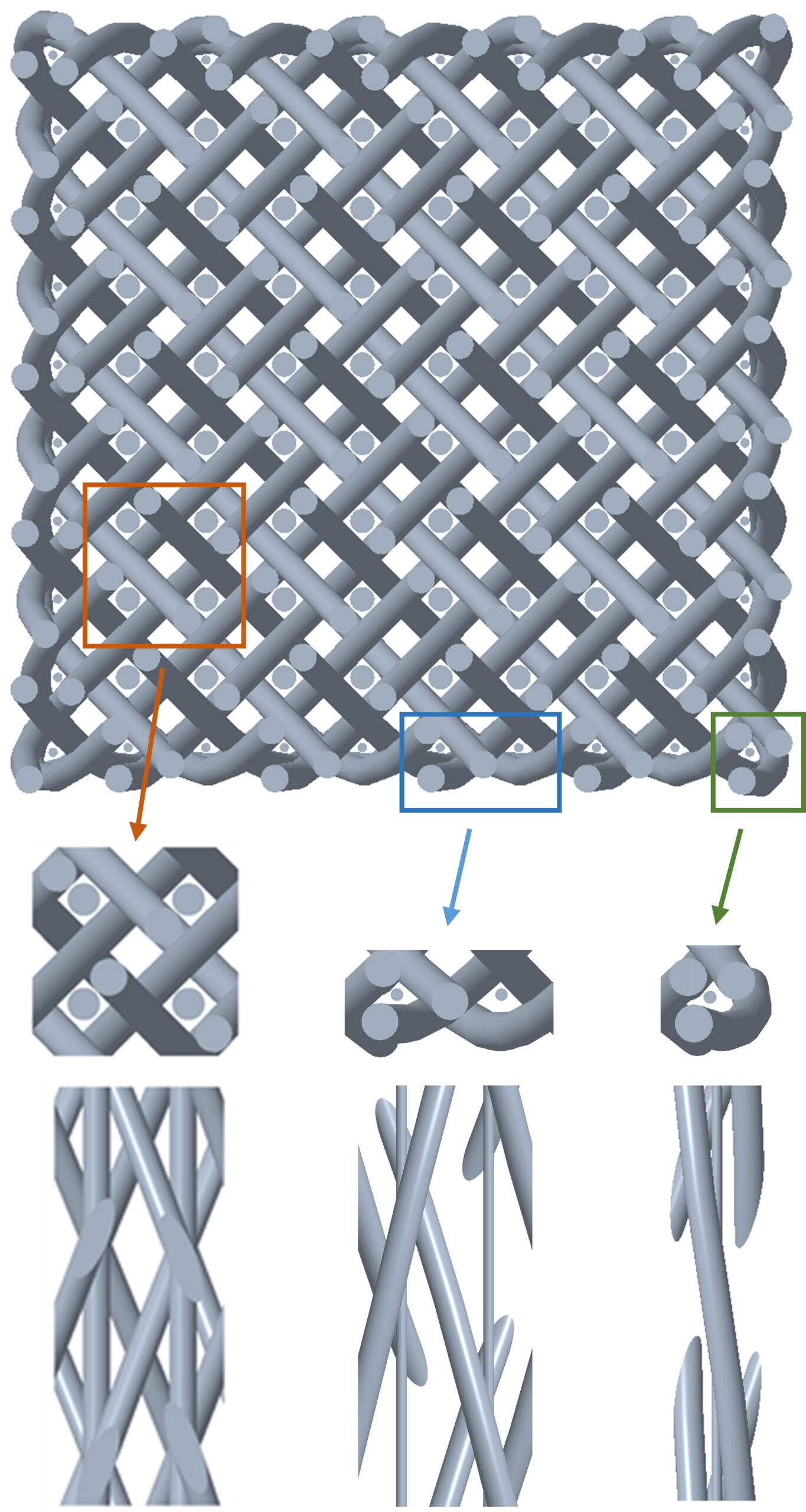
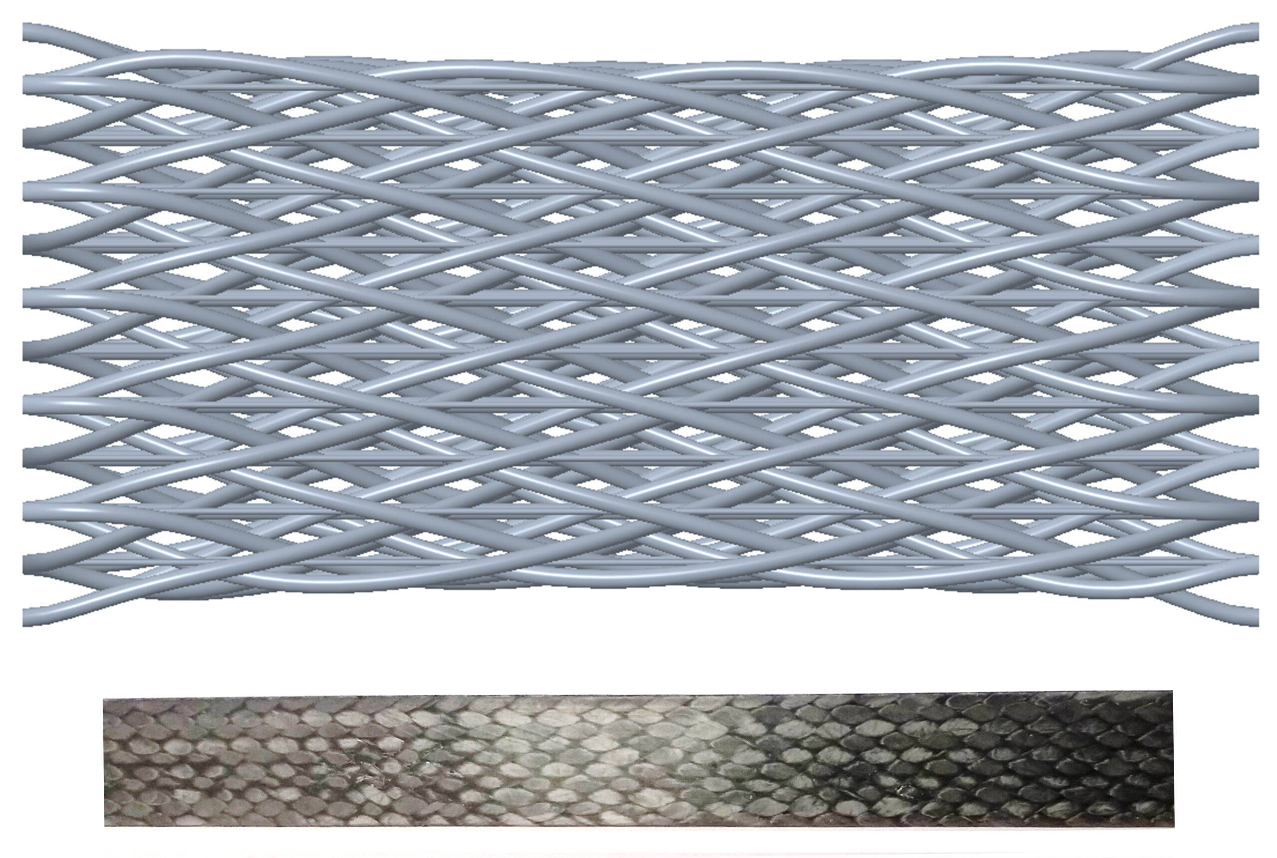
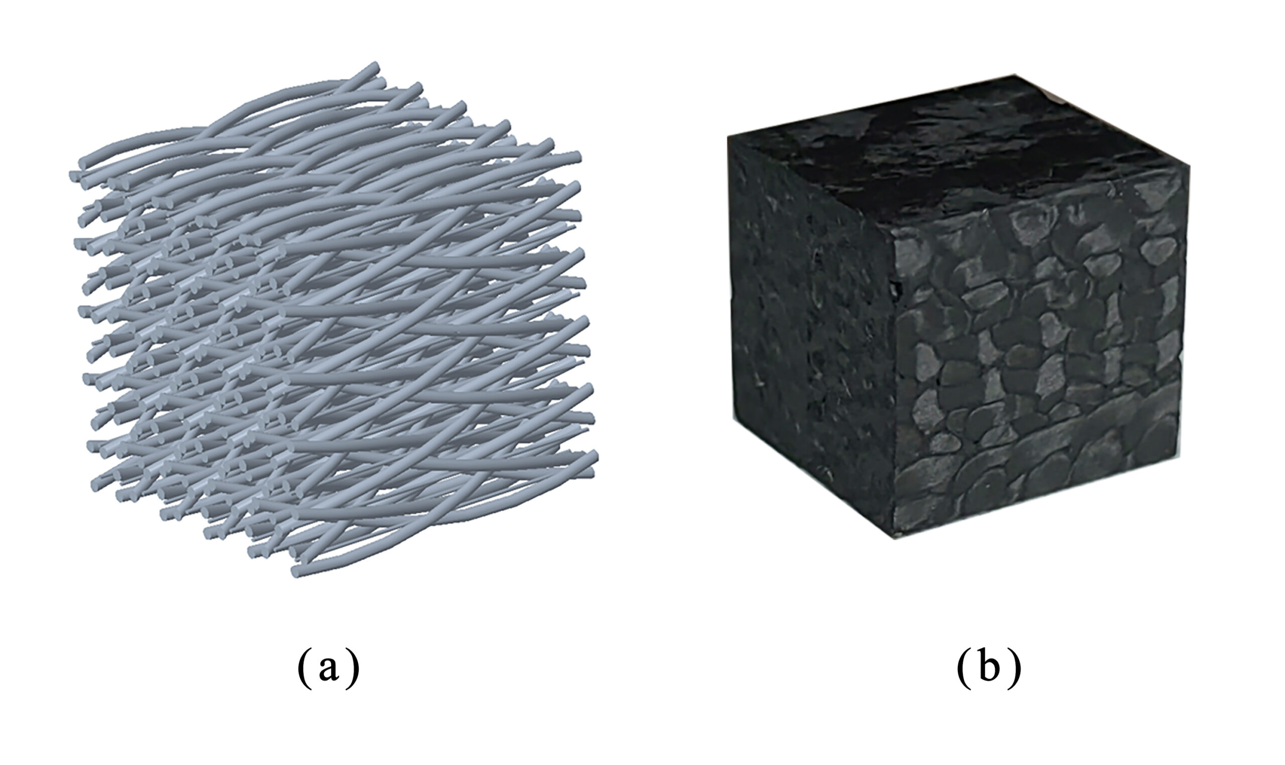
In order to further verify the rationality of the simulation system, a 3D five-directional braided composites with the braiding angle of 22.3° and the array of yarn carries (m×n+axis) of 11×11+10 is taken as an example to establish the simulation model correspond to the test specimen in this paper, the size of which is about 10×10×10\(\text{m}{{\text{m}}^{3}}\). As shown in Figure 3, Figure 4 and Figure 5. It is found that the braided yarns in the inner region are approximately regarded as the straight lines, while the braided yarns in the surface and corner region are squeezed more seriously and regarded as the curve lines in the macro-scale simulation model. And the overall morphology of the macro-scale simulation model is similar to the practical fabric, which can better represent the interwoven structure of yarns, and can obtain the morphology of yarns at any position of 3D braided composites. It can be seen that the macro-scale simulation model in this paper is correspond to the actual braided structure, which indicates that the simulation system of 3D five-directional braided composites is effective. By changing the input design parameters, the macro-scale structural model of 3D five-directional braided composites with different braiding parameters can be established.
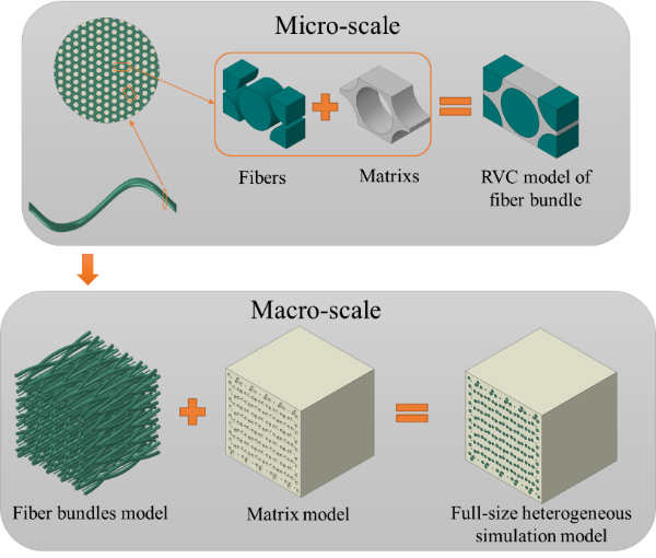
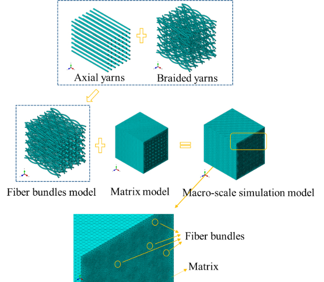
In this paper, the full-size heterogeneous model of 3D five-directional braided composites is established by the computer simulation system. The model includes the fiber bundles model and matrix model, as shown in Figure 6. The elastic constants of the micro-scale fiber bundle is usually taken as the basic material parameters of the mac-ro-scale fiber bundles model. Thus, the multi-scale (i.e. macro-scale and micro-scale) heterogeneous analysis is realized.
In this paper, Hashin failure criterion and Chang-Chang failure criterion are used to determine the damage of fiber and matrix in the fiber bundles model, and Mises strength criterion and ductile and shear criterion are used to evaluate the damage of the matrix model. The stiffness degradation model and displacement-based degradation model are used to realize the damage evolution of the fiber bundles model and the matrix model respectively.
The detail description of strain-based failure criteria in fiber bundles model is as follows [38-43]:
For fiber tensile failure (Strain-based Hashin fiber during stretching, \({\varepsilon _{11}} \geqslant 0\) )
\[\label{e1} \left(\frac{\varepsilon_{11}}{\varepsilon_{11}^t}\right)^2+\alpha\left(\frac{\varepsilon_{12}}{\gamma_{12}}\right)^2+\alpha\left(\frac{\varepsilon_{13}}{\gamma_{12}}\right)^2= \begin{cases}\geq 1 & \text { failure, } \\ <1 & \text {nofailure. }\end{cases} \tag{1}\]
For fiber compression failure (Strain-based Hashin fiber during compressing, \({\varepsilon _{11}} < 0\) )
\[\label{e2} -\frac{\varepsilon_{11}}{\varepsilon_{11}^c}= \begin{cases}\geq 1 & \text { failure ,} \\ <1 & \text {nofailure.}\end{cases} \tag{2}\]
For matrix tensile failure (Strain-based Chang-Chang matrix during stretching, \({\varepsilon _{22}} + {\varepsilon _{33}} \geqslant 0\) )
\[\label{e3} \frac{\varepsilon_{22}^2+\varepsilon_{33}^2}{\left(\varepsilon_{0,2}^t\right)^2}+\frac{\varepsilon_{12}^2+\varepsilon_{13}^2}{\varepsilon_{0,12}^2}= \begin{cases}\geq 1 & \text { failure, } \\ <1 & \text {nofailure.}\end{cases} \tag{3}\]
For matrix compression failure (Strain-based Chang-Chang matrix during compressing, \({\varepsilon _{22}} + {\varepsilon _{33}} < 0\) )
\[\label{e4} \frac{1}{4}\left(\frac{\varepsilon_{22}^2}{\varepsilon_{0,12}^2}\right)+\frac{\varepsilon_{12}^2}{\varepsilon_{0,12}^2}+\frac{\left(\varepsilon_{0,2}^c\right)^2 \varepsilon_{22}}{4 \varepsilon_{0,12}^2 \varepsilon_{0,2}^c}-\frac{\varepsilon_{22}}{\varepsilon_{0,2}^c}= \begin{cases}\geq 1 & \text { failure, } \\ <1 & \text {nofailure. }\end{cases} \tag{4}\]
The stiffness degradation model in fiber bundles model is shown in Table 1. Where \({F_f} = 1 – 0.93{e^{{{ct} \mathord{\left/ {\vphantom {{ct} {tt}}} \right. } {tt}} – 1}}\) , \({F_{fc}} = 1 – 0.86{e^{{{ct} \mathord{\left/ {\vphantom {{ct} {tt}}} \right. } {tt}} – 1}}\) , \({F_m} = 1 – 0.8{e^{{{ct} \mathord{\left/ {\vphantom {{ct} {tt}}} \right. } {tt}} – 1}}\) and \({F_{mc}} = 1 – 0.6{e^{{{ct} \mathord{\left/ {\vphantom {{ct} {tt}}} \right. } {tt}} – 1}}\). \({D_f}\) ,\({D_{fc}}\) , \({D_m}\) and \({D_{mc}}\) correspond to the damage variables of each component of materials under four damage modes respectively. When the damage variable is 1, it means that failure begins to occur inside the material under impact loading, and stiffness reduction begins to be carried out according to Table 1 until the deletion of failure elements. When the damage variable is 0, it means that the material has no damage and no stiffness reduction is required. \({e^{{{ct} \mathord{\left/ {\vphantom {{ct} {tt}}} \right. } {tt}} – 1}}\) represents the variable that controls the continuous attenuation of stiffness of the material, ct means the current time, and tt means the total time required for kinetic energy of the bullet to go from maximum to zero.
| Fiber Tensile Failure | Fiber Compression Failure | Matrix Tensile Failure | Matrix Compression Failure |
| $$D_f$$ =1 | $$D_fc$$=1 | $$D_m$$ =1 | $$D_mc$$=1 |
| $$(E_1)*F_f$$ | $$(E_1)*F_fc$$ | $$(E_2,G_12,G_23)*F_m$$ | $$(E_2,G_12,G_23)*F_mc$$ |
The detail description of failure criteria in the matrix model is as follows:
For Mises strength criteria,
\[\label{e5} {({\sigma _1} – {\sigma _2})^2} + {({\sigma _1} – {\sigma _3})^2} + {({\sigma _3} – {\sigma _2})^2} + 6(\tau _{12}^2 + \tau _{23}^2 + \tau _{31}^2) = 2\sigma _m^2 , \tag{5}\] where \({\sigma _m}\) is the failure strength of matrix.
For ductile and shear criterion, the shear criterion is a phenomenological model used to predict the initiation of damage caused by local shear bands. It is assumed that the equivalent plastic strain \(\varepsilon _S^{pl}\) is a function of shear stress ratio and strain rate at the beginning of damage.
\[\label{e6}{\varepsilon _S^{pl}}({\theta _S},\dot {\varepsilon _S^{pl}}) = \frac{{\varepsilon _S^ + \sinh [f({\theta _S} – \theta _S^ – )] + \varepsilon _S^ – \sinh [f(\theta _S^ + – {\theta _S})]}}{{\sinh [f(\theta _S^ + – \theta _S^ – )]}}\tag{6}\] where \({\theta _S} = {{(q + {k_S}p)} \mathord{\left/ {\vphantom {{(q + {k_S}p)} {{\tau _{\max }}}}} \right. } {{\tau _{\max }}}}\) is the shear stress, \({\tau _{\max }}\) is the maximum shear stress, and \({k_S}\) is the material parameter. The criterion for damage initiation is met when the equation \({\omega _S} = \int {\frac{{{\text{d}}{{ \varepsilon }^{pl}}}}{{\varepsilon _S^{pl}({\theta _S},\dot \varepsilon _S^{pl})}}} = 1\) is satisfied, where \({\omega _S}\) is a state variable that increases monotonically with plastic deformation. The plastic deformation is proportional to the increment of the equiv-alent plastic strain. The increment of \({\omega _S}\) is calculated by the equation \(\Delta {\omega _S} = \frac{{\Delta {{ \varepsilon }^{pl}}}}{{\varepsilon _S^{pl}({\theta _S},{{\dot \varepsilon }^{pl}})}} \geqslant 0\) . The displacement-based degradation model (failure displacement is 0.001) is used as the basis for matrix damage evolution.
Figure 7 shows the meshing of macro-scale simulation model. There are many holes, sharp corners and flakes in the matrix model due to the extrusion deformation between the fiber bun-dles and the matrix, which makes the matrix structure more complex. Therefore, C3D4 solid element is used to free meshing on the matrix model, and C3D8R solid element is used to sweep meshing on the fiber bundles model.
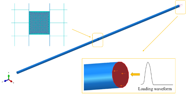
Set the incident bar and transmission bar as rigid rods, general contact between the bars and the specimen, surface-to-surface contact between the fiber bundles and the matrix, and ideal bonding in the whole model. Figure 8 shows the SHPB impact compression finite element model and the transverse loading mode. The loading signal obtained from the SHPB test is the loading waveform in the finite element analysis. Table 2 and Table 3 show the material properties and strength properties of fiber bundle and matrix respectively.
| Components | Material Property Parameters | |||||
| – | $$E_11$$ | $$E_22$$ | $$G_12$$ | $$G_23$$ | $$v_12$$ | $$v_23$$ |
| Fiber Bundle | 172.95 | 7.43 | 3.35 | 2.71 | 0.36 | 0.37 |
| – | $$E_m$$ | $$v_m$$ | $$G_m$$ | – | – | – |
| Matrix | 3.50 | 0.35 | 1.30 | – | – | – |
| Note: 1-fiber direction, 2,3-transverse direction. \({E_{ij}}\) and \({G_{ij}}\) in GPa. | ||||||
| Components | $$X_11^T$$ | $$X_11^C$$ | $$X_22^T$$ | $$X_22^C$$ | $$X_33^T$$ | $$X_33^C$$ | $$S_12$$ | $$S_13$$ | $$S_23$$ |
| Fiber bundle | 1411.2 | 988 | 66.1 | 199 | 66.1 | 199 | 48.1 | 48.1 | 45.6 |
| Matrix | 60 | 80 | – | – | – | – | 60 | – | – |
| Note: \({X_{ij}}\) and \({S_{ij}}\)in MPa. | |||||||||
By means of ABAQUS/Explict solver, the impact compression numerical simulation of 3D five-directional braided composites is carried out to investigate the influences of strain rate and braiding angle on the dynamic mechanical properties and fracture characteristics. And the dynamic failure mechanism of the matrix and fiber bundles during compression is revealed.
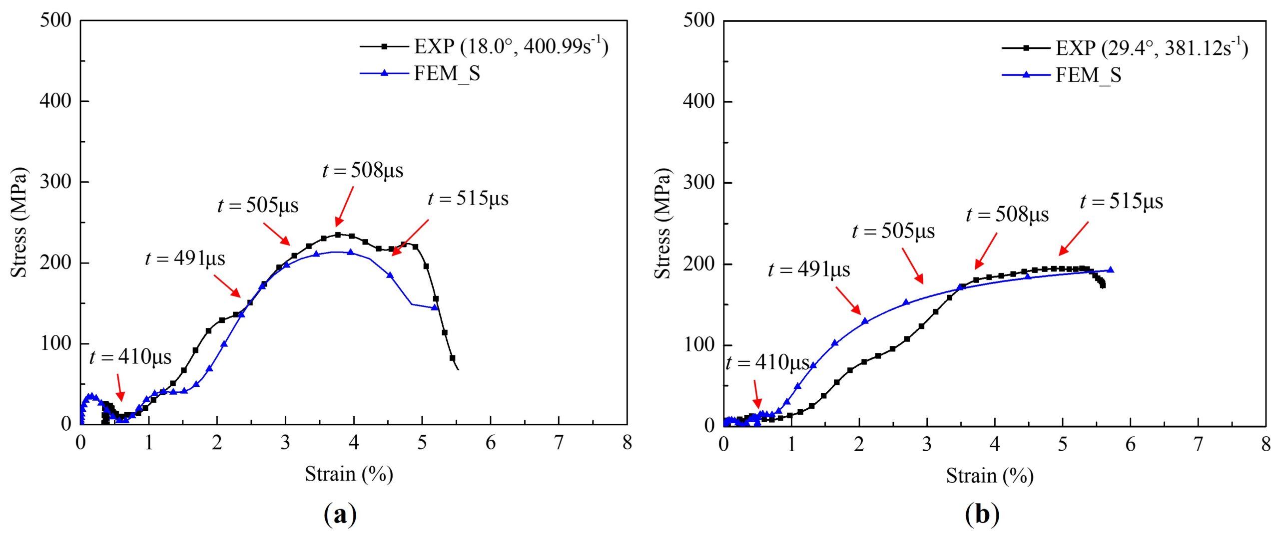
Figure 9, Table 4 and Table 5 show the comparison between the test and numerical simulation results of the stress-strain curves and the main mechanical property parameters of specimens changing with the strain rate and braiding angle under transverse impact compression respectively. FEM_S in the figure is short for FEM Simulation Model. The numerical simulation results are in good agreement with the experimental results, which indicating that the established finite element model can be used to analysis the impact compression mechanical response of 3D five-directional braided composites effectively. With the increase of strain rate, the transverse dynamic peak stress \(\sigma _T^{RC}\) , peak strain \(\varepsilon _T^{RC}\) and compression modulus\(E_T^{RC}\) increase gradually. But with the increase of braiding angle, the transverse dynamic peak stress \(\sigma _T^{BC}\) and compression modulus \(E_T^{BC}\) decrease, and the peak strain \(\varepsilon _T^{BC}\) increases gradually.
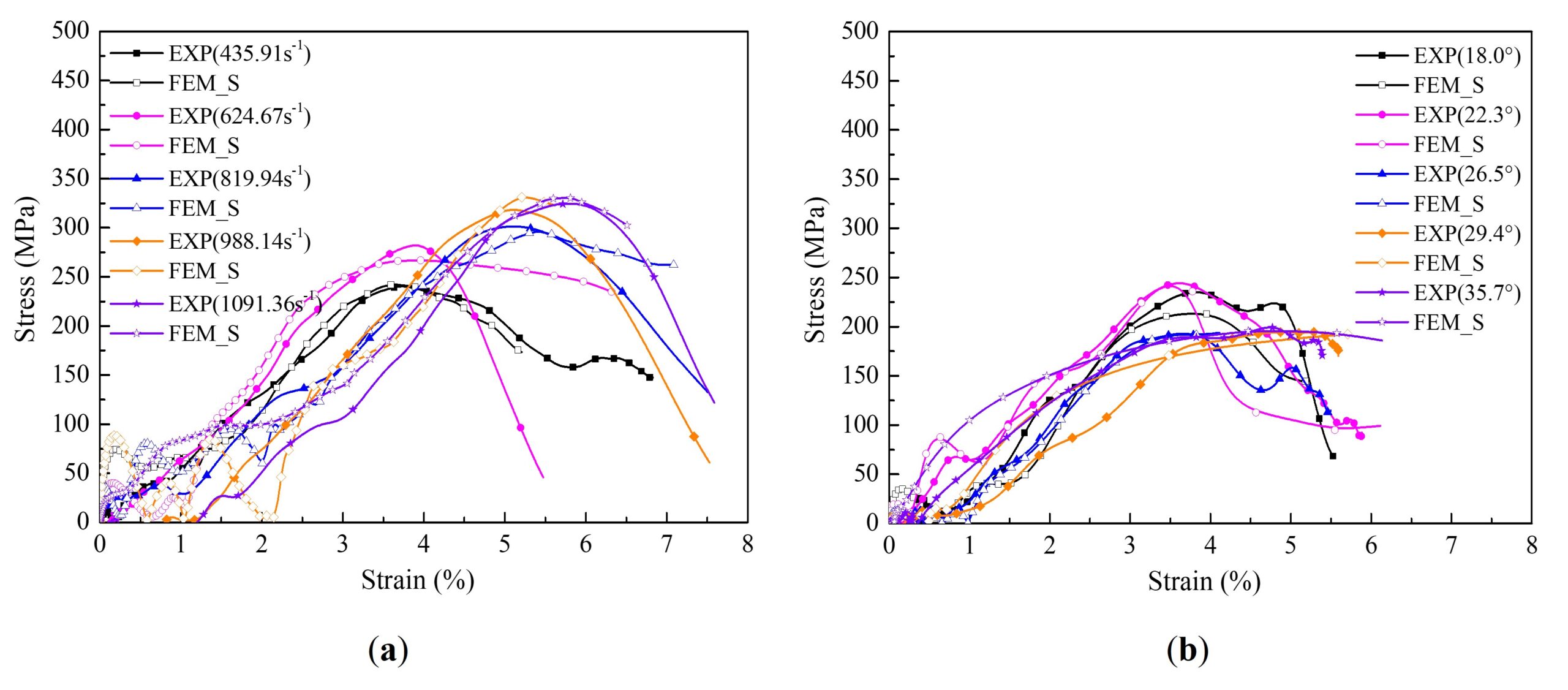
| $$\dot{\varepsilon }({{\text{s}}^{-1}})$$ | \(\sigma _{T}^{RC}\left( \text{MPa} \right)\) | \(E_{T}^{RC}\left( \text{GPa} \right)\) | \(\varepsilon _{T}^{RC}\left( \text{1}{{\text{0}}^{-2}} \right)\) | ||||||
| EXP | FEM_S | Deviation | EXP | FEM_S | Deviation | EXP | FEM_S | Deviation | |
| 435.91 | 241.34 | 242.15 | 0.34% | 7.51 | 7.39 | 1.60% | 3.92 | 3.69 | 5.87% |
| 624.67 | 272.93 | 266.80 | 2.25% | 9.24 | 8.24 | 10.82% | 3.84 | 3.96 | 3.13% |
| 819.94 | 297.05 | 296.64 | 0.14% | 9.79 | 8.57 | 12.46% | 5.27 | 5.12 | 2.85% |
| 988.14 | 313.71 | 331.19 | 5.57% | 10.92 | 9.57 | 12.36% | 5.08 | 5.21 | 2.56% |
| 1091.36 | 323.49 | 330.59 | 2.19% | 10.54 | 9.64 | 8.54% | 5.62 | 5.74 | 2.14% |
| $$\alpha $$(°) | $$\sigma _{T}^{BC}\left( \text{MPa} \right)$$ | $$E_{T}^{BC}\left( \text{GPa} \right)$$ | $$\varepsilon _{T}^{BC}\left( \text{1}{{\text{0}}^{-2}} \right)$$ | ||||||
| EXP | FEM_S | Deviation | EXP | FEM_S | Deviation | EXP | FEM_S | Deviation | |
| 18.0 | 235.99 | 213.60 | 9.49% | 8.89 | 10.3 | 15.86% | 3.88 | 3.59 | 7.47% |
| 22.3 | 241.34 | 235.06 | 2.60% | 7.51 | 7.41 | 1.33% | 3.92 | 3.67 | 6.38% |
| 26.5 | 195.78 | 192.28 | 1.79% | 7.03 | 7.30 | 3.84% | 3.82 | 3.94 | 3.14% |
| 29.4 | 199.01 | 184.05 | 7.52% | 6.36 | 6.57 | 3.30% | 4.73 | 4.48 | 5.29% |
| 35.7 | 188.17 | 179.82 | 4.44% | 6.22 | 6.41 | 3.05% | 4.68 | 4.67 | 0.21% |
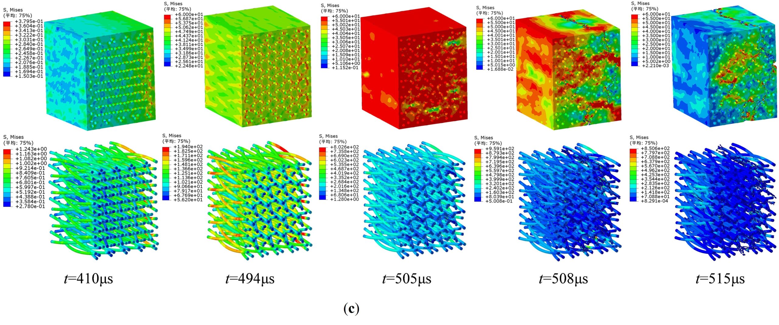
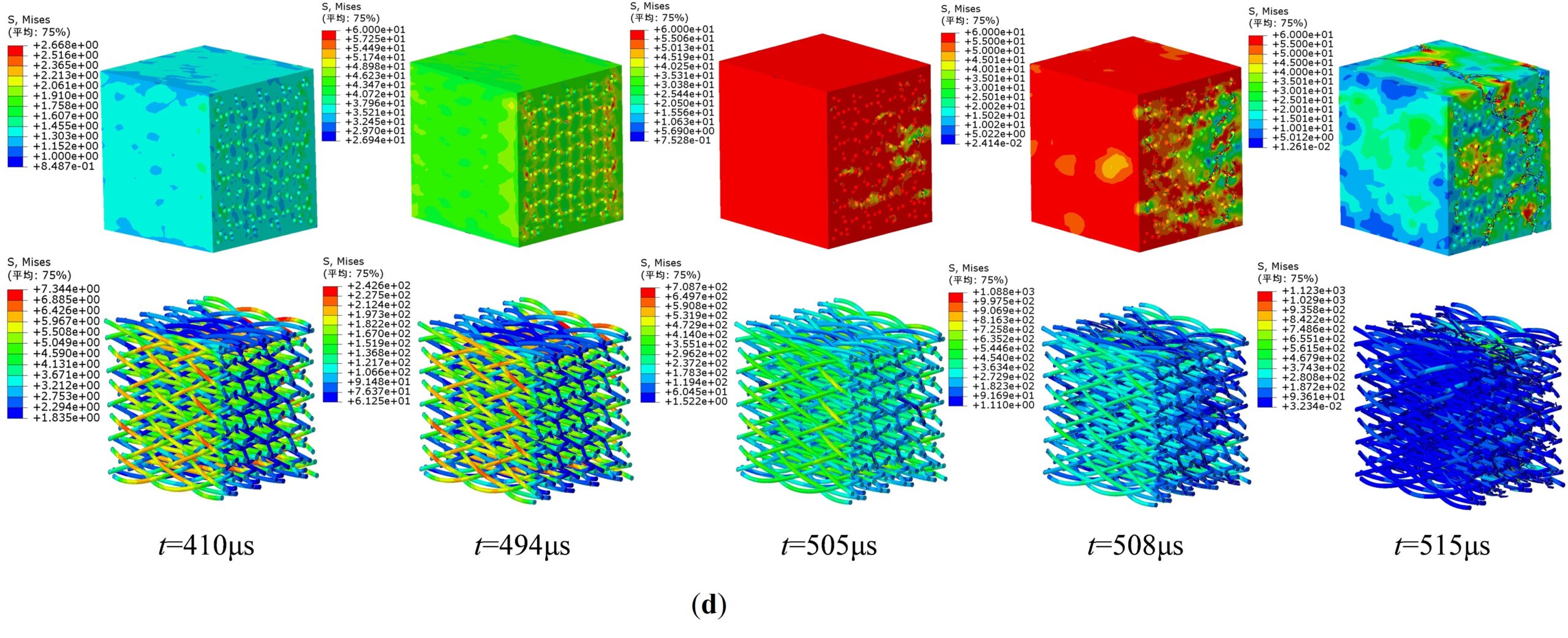
In order to further study the stress distribution and dynamic failure variation of matrix and fiber bundles in 3D five-directional braided composites, the numerical simulation results of the model under braided angle of 22.3° and strain rate of 624.67\({{\text{s}}^{-1}}\) were taken as an example. The results were obtained by the primary propagation of stress wave acting between incident bar and transmission bar. Figure 10 and Figure 11 show the numerical simulation results of impact compression failure process of matrix and fiber bundles respectively.
Figure 10 shows as follows:
the period from t=380\(\mu\)s to t=481\(\mu\)s can be represented as the stage of transverse compression deformation of matrix. The stress in the matrix increases gradually, and the matrix is compacted with no micro cracks initiation. The compression deformation occurs only along the loading direction, and the stress is highly concentrated along the braided structure,
the period from t=380\(\mu\)s to t=481\(\mu\)s can be represented as the stage of the crack initiation and propagation of matrix. The micro cracks initiate first at the contact position between matrix and fiber bundles, and then expand and connect with each other around the cracks. The stress around the cracks decreases, but the overall structure can still continue to bear the loading,
the period from t=380\(\mu\)s to t=481\(\mu\)s can be represented as the unloading stage of matrix. The cracks extend further and form two main fracture planes eventually. The overall stress of matrix decreases rapidly until it has no bearing capacity.
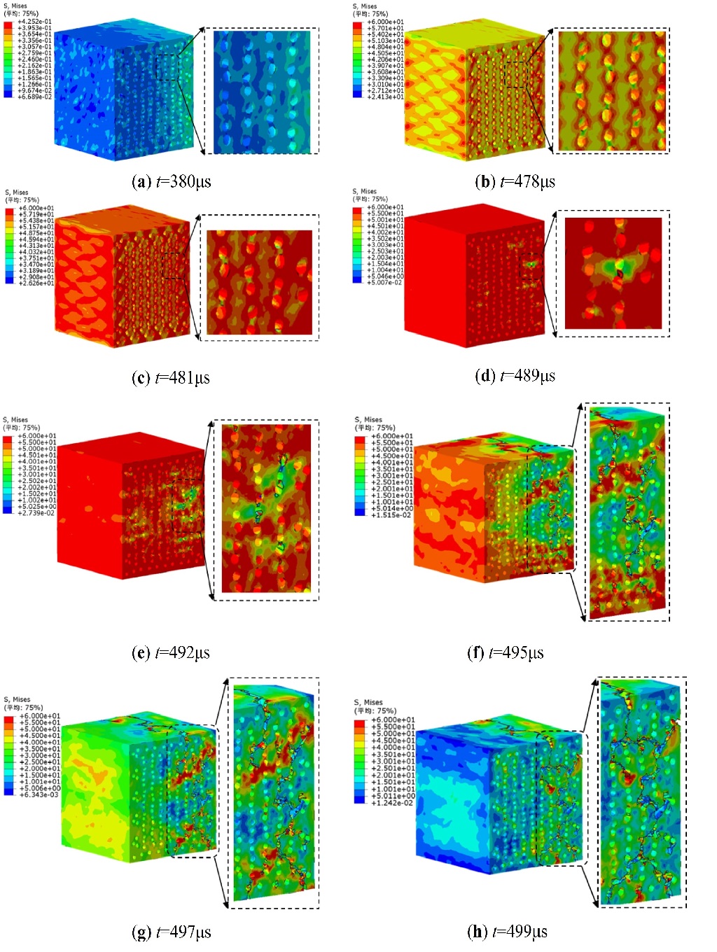
Figure 11shows as follows:
the period from t=380\(\mu\)s to t=481\(\mu\)s can be represented as the stage of transverse compression deformation of fiber bundles. The stress in the fiber bundles increases gradually. And the bearing capacity of the axial yarns is higher than that of braided yarns slightly with the in-crease of time, which indicates that the axial yarns and braided yarns in the fiber bundles bear the load together,
the period from t=380\(\mu\)s to t=481\(\mu\)s can be represented as the stage of damage failure of fiber bundles. The fiber bundles break gradually at the position corresponding to the crack propagation of the matrix, and the overall stress of fiber bundles decreases rapidly,
the period from t=380\(\mu\)s to t=481\(\mu\)s can be represented as the further failure stage of fiber bundles. The fiber bundles break further at the position corresponding to the location of the two fracture planes of matrix. But most of the fiber bundles at other positions remain intact basically.
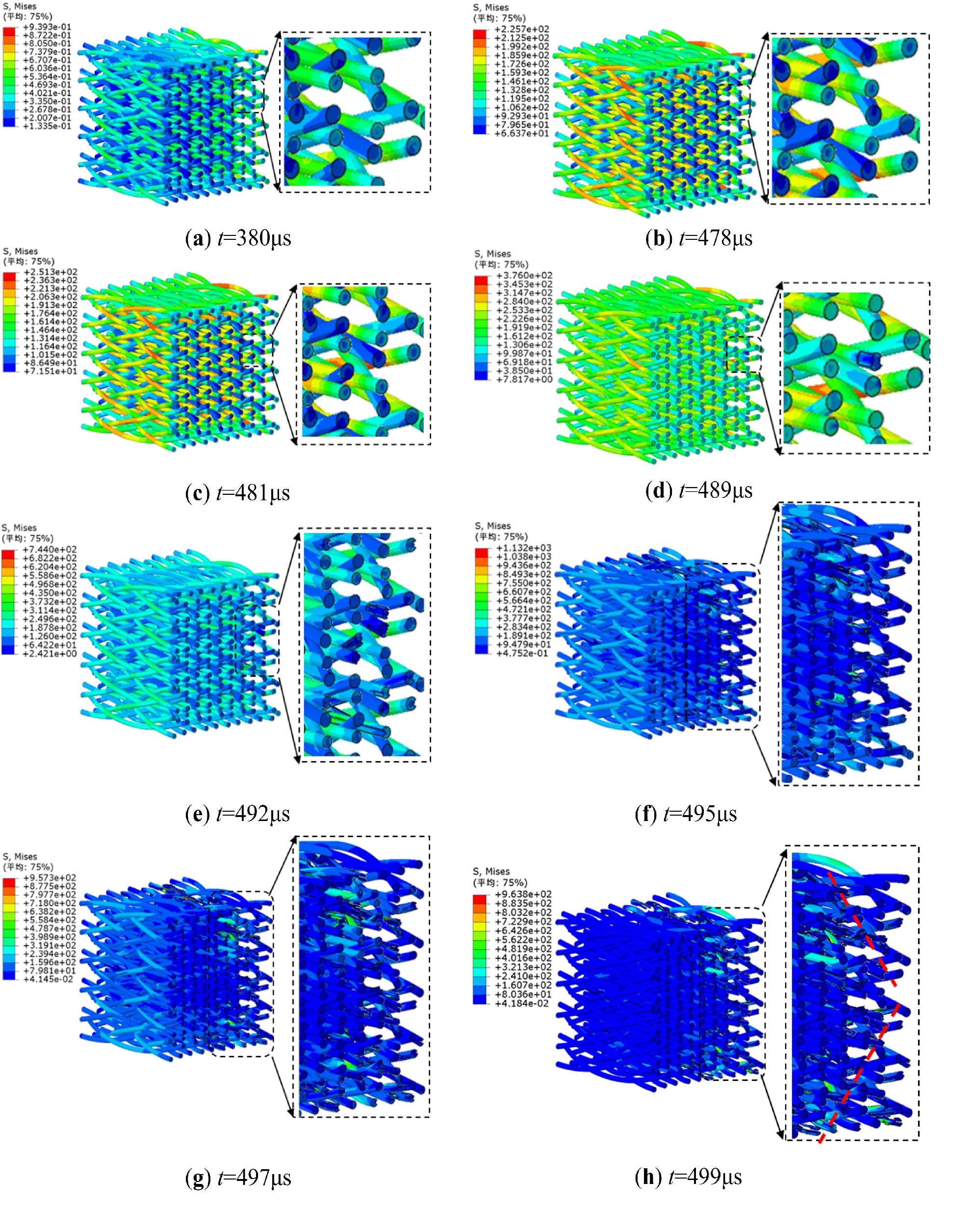
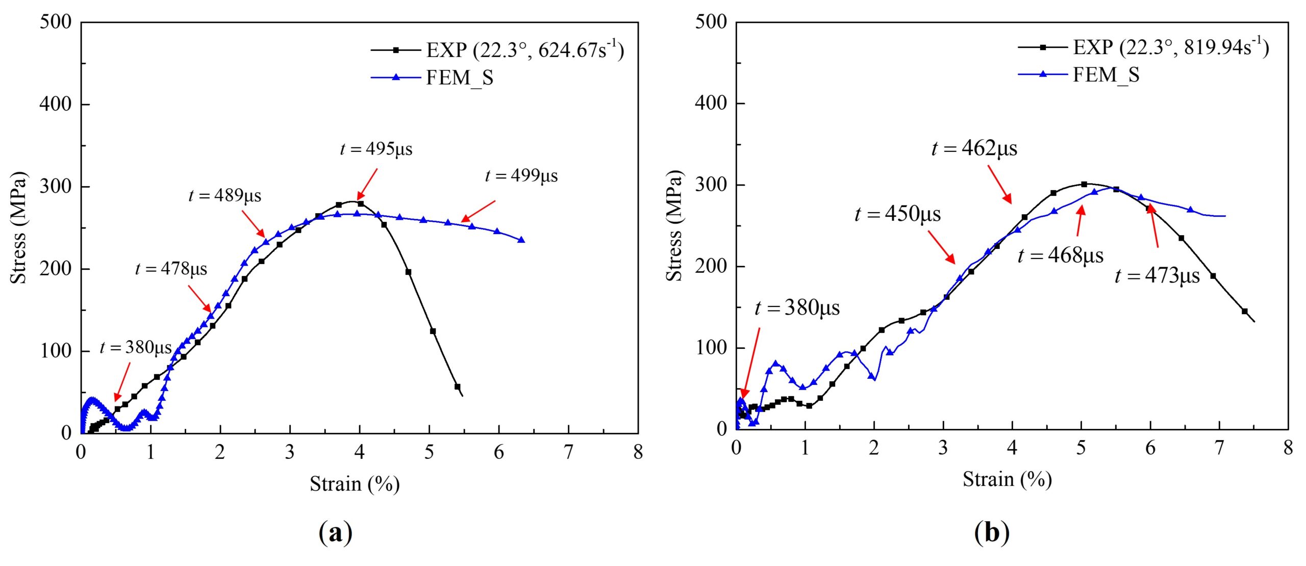
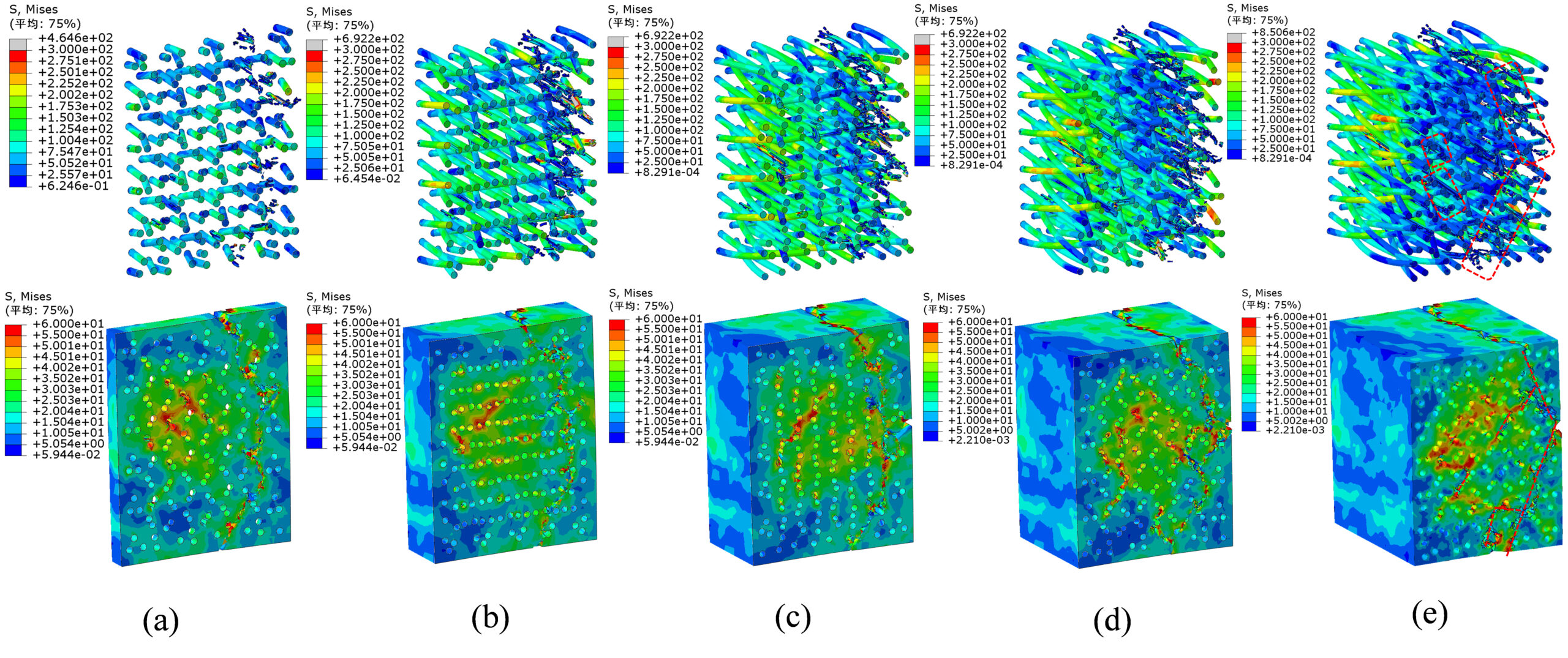
Figure 12 shows the stress distribution and dynamic failure characteristics of the matrix and fiber bundles at different moments with braiding angle of 22.3° and strain rate of 624.67\({{\text{s}}^{-1}}\) and 819.94 \({{\text{s}}^{-1}}\) respectively. It can be seen that the laws of dynamic deformation damage of the matrix and fiber bundles are similar roughly under different strain rates. However, with the increase of strain rate, the time histories of dynamic deformation damage of matrix and fiber bundles decreases gradually, indicating more serious damage of the specimens with the increase of strain rate.
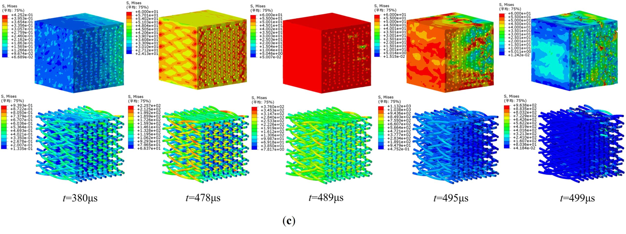
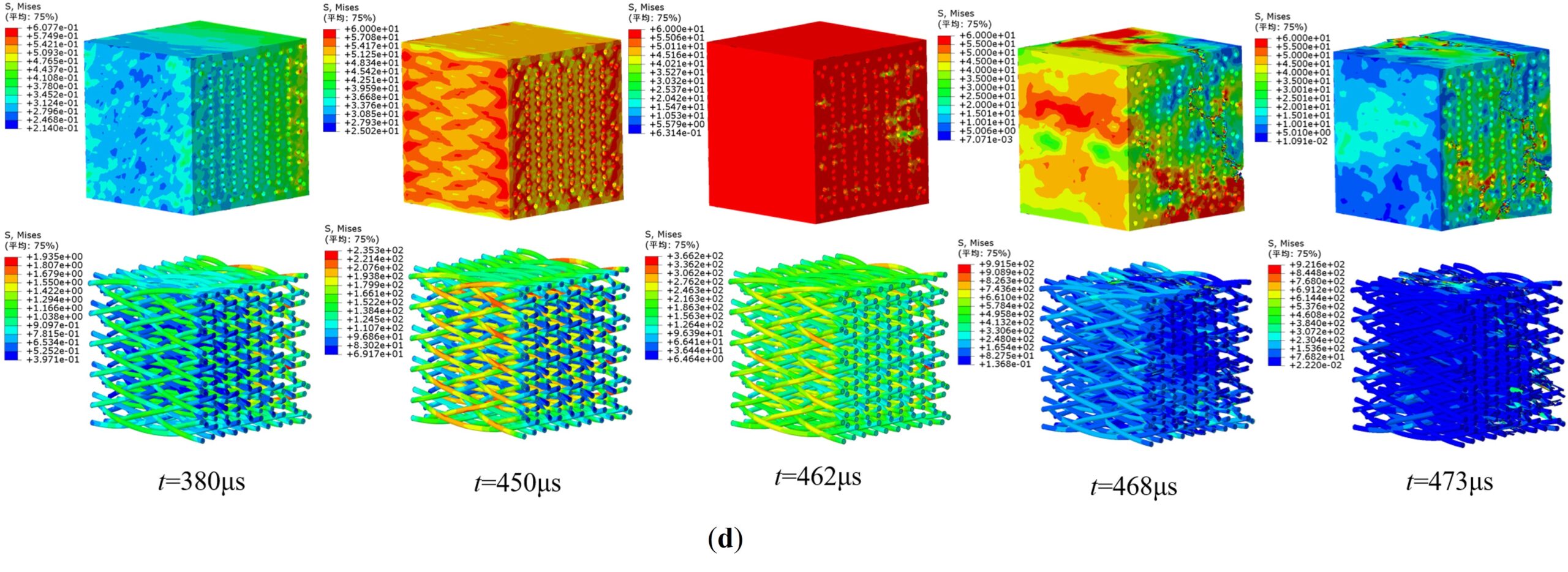
Figure 13 shows the stress distribution and dynamic failure characteristics of the matrix and fiber bundles at different moments with braiding angle of 18.0° and 29.4° under the same impact pressure respectively. It can be seen that the time histories of dynamic deformation damage of matrix and fiber bundles are concordance basically under different braiding angle. However, with the increase of braiding angle, the structure of the materials becomes more compact, and the matrix undergoes higher damage with small braiding angle at the same moment.
Figure 14 shows the stress nephograms of final failure characteristics of matrix and fiber bundles with braiding angle of 18.0° and strain rate of 400.99 \({{\text{s}}^{-1}}\) at different thickness slices. It can be seen that the failure of fiber bundles and matrix corresponds to each other and mainly concentrates on two main fracture shear planes.
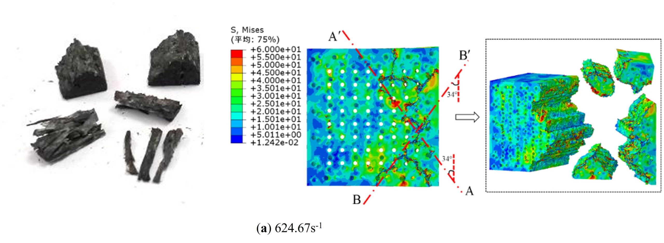
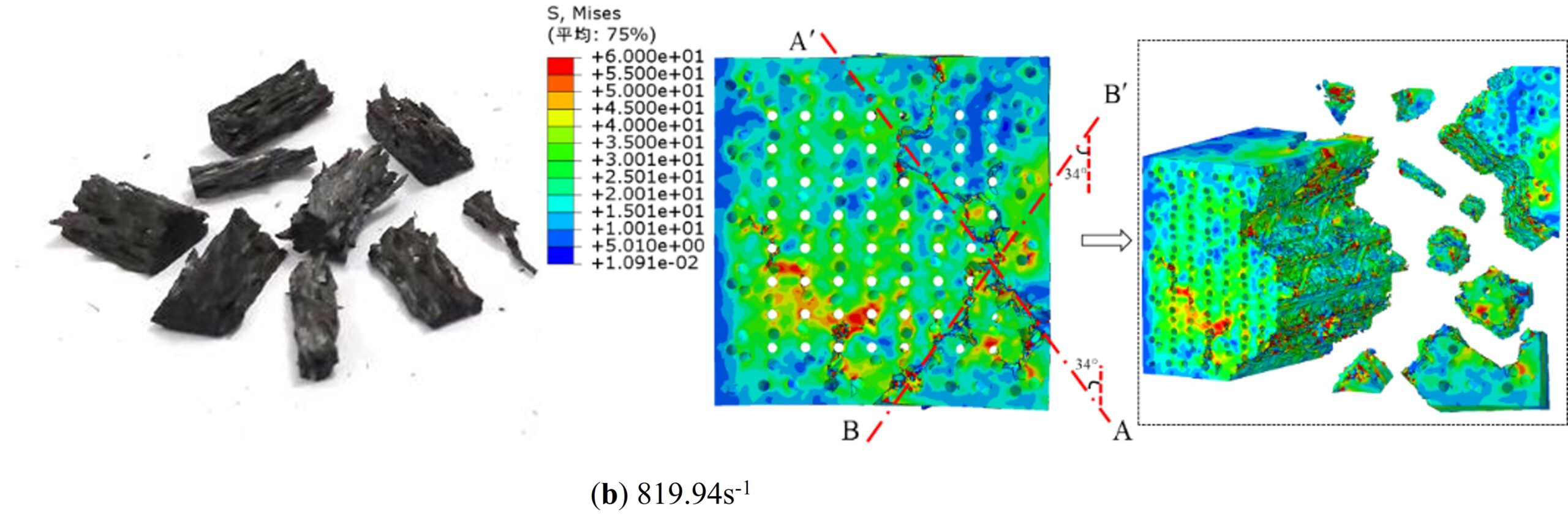
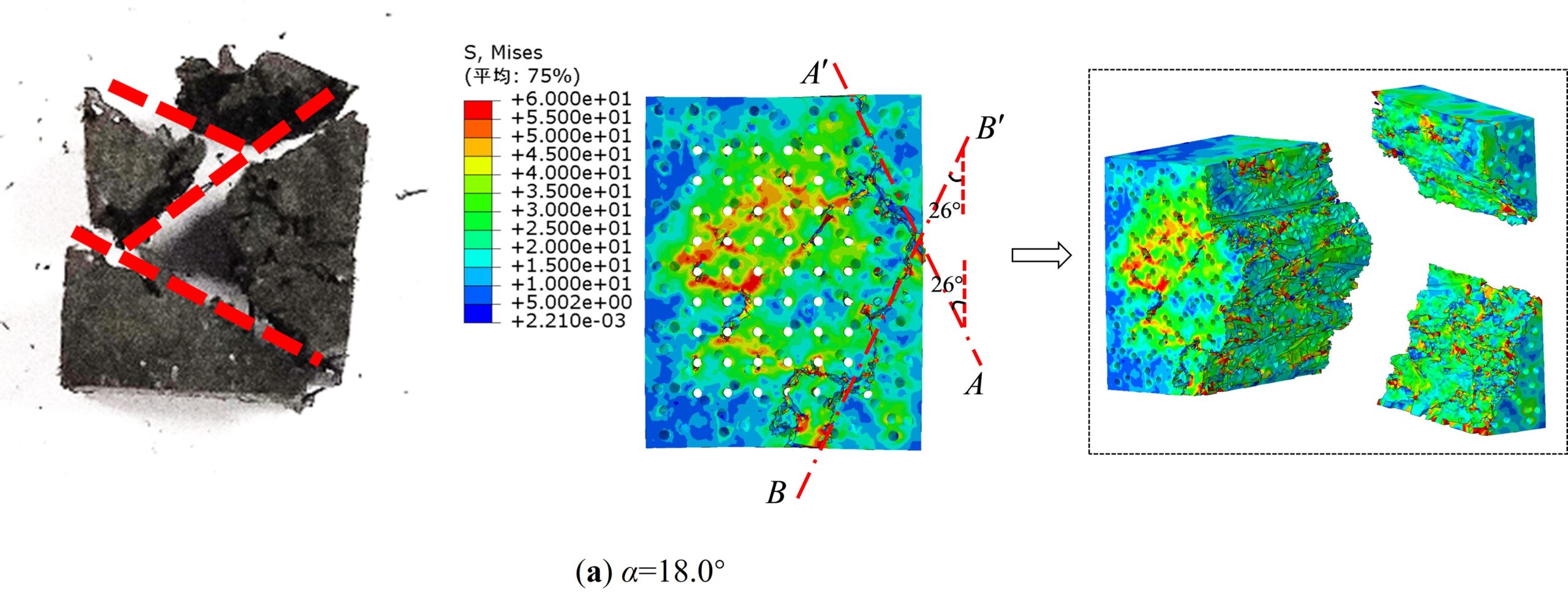
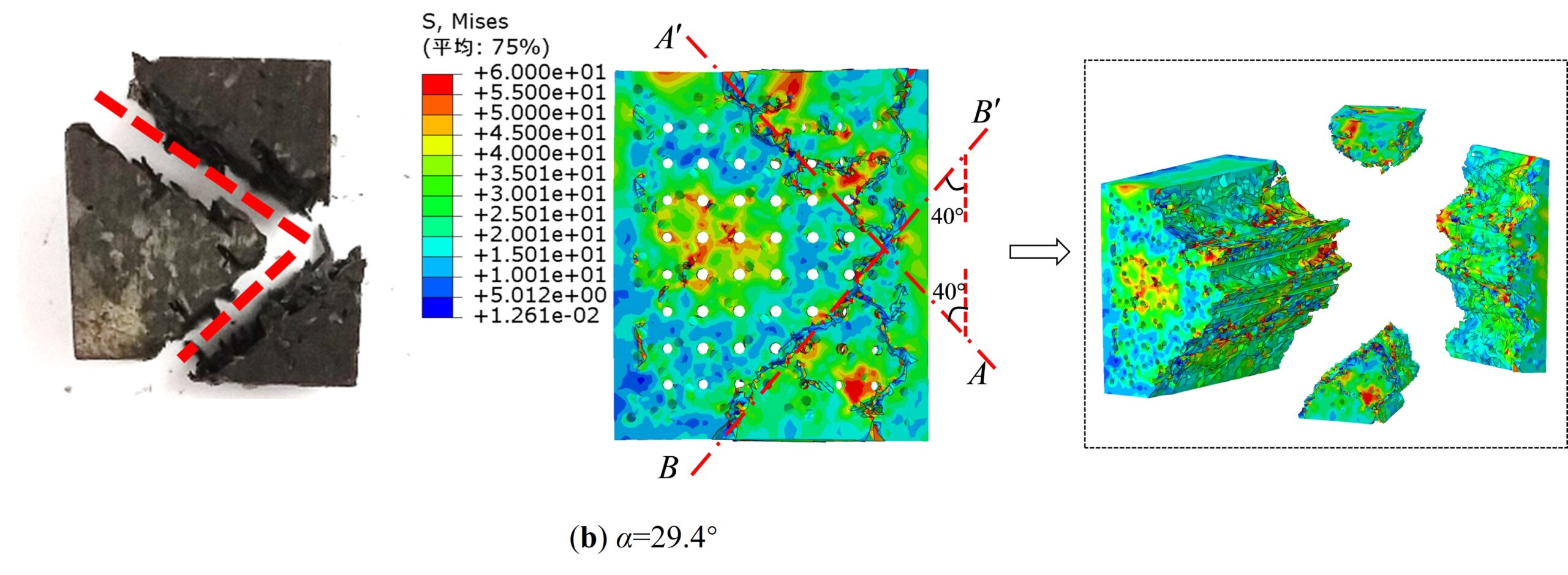
In order to further study the failure mechanism of specimens affected by the strain rate and braiding angle, the comparison results between the test and numerical simulation results of the fracture characteristics of specimens are presented in Figure 15 and Figure 16.
Figure 15 shows that the numerical simulation results are in good agreement with the test results. The broken specimens are mostly the columnar block with polygonal section under transverse impact compression. With the increase of strain rate, the matrix undergoes higher damage, and the broken specimens’ volume decreases. And it can be seen two main fracture shear planes in the specimens from the numerical simulation nephograms. The included angle between the fracture shear planes and the vertical direction (perpendicular to the loading direction) is about 34°, which corresponds to the internal braiding angle of the material with braiding angle of 22.3° approximately.
Figure 16 shows that the included angle between the two main fracture shear planes and the vertical direction in the simulation is different. The included angle is about 26° in the specimen with braiding angle of 18.0°, while it is about 40° in the specimen with braiding angle of 29.4°. In view of the braiding angle of 18.0° and 29.4°, the internal braiding angle are \(\gamma {\text{ = }}24.68^\circ\) and \(\gamma {\text{ = }}38055^\circ\) respectively. This indicates that the included angle between the fracture shear planes and the vertical direction is consistent with the corresponding internal braiding angle with the increase of braiding angle under transverse impact compression.
The macro-scale heterogeneous simulation structure model is established based on the spatial trajectories of fiber bundles in 3D five-directional braided composites. The impact compression numerical simulation of the material is carried out using the multi-scale analysis method. The effects of strain rate and braiding angle on the dynamic mechanical properties and fracture characteristics of the material is studied, and the dynamic failure mechanism of the matrix and fiber bundles during the impact compression process is revealed. The main research results are summarized as follows:
The full-scale simulation model of 3D five-directional braided composites established in this paper is effective, and the numerical simulation results agree well with the experimental results. The simulation model can reflect the real time dynamic failure characteristics of fiber bundles or matrix, and describe the whole process of the dynamic failure of the specimen clearly, that is, cracks from initiation generation to extension to penetration through the whole specimen.
The matrix fracture and the shear failure of the fiber bundles are presented simultaneously under the transverse impact compression. The dynamic failure process of matrix can be divided into three stages: transverse compression deformation stage, cracks initiation and propagation stage and unloading stage. The dynamic failure process of fiber bundles can also be divided into three stages: transverse compression deformation stage, damage failure stage and further failure stage. With the increase of strain rate, the time histories of dynamic deformation damage of matrix and fiber bundles decreases gradually. But the matrix undergoes higher damage with small braiding angle at the same moment.
The broken specimens are mostly the columnar block with polygonal section under transverse impact compression. The failure of fiber bundles and matrix mainly concentrates on two main fracture shear planes. And the included angle between the fracture shear planes and the vertical direction (perpendicular to the loading direction) is consistent with the corresponding internal braiding angle of the specimens with the increase of braiding angle.
Methodology, C.C.; Software, C.C. and M.X.; Investigation, C.C. and W.W.; Resources, C.C.; Writing—original draft preparation, C.C.; Writing—review and editing, H.Y. and W.W.; Visualization, C.C.; Supervision, C.C. and H.Y.; Project administration, C.C.; Funding acquisition, C.C. All authors have read and agreed to the published version of the manuscript.
All authors reviewed the results, approved the final version of the manuscript and agreed to publish it.
The raw/processed data required to reproduce these findings cannot be shared at this time be-cause the data also form part of an ongoing study.
The authors declare that they have no known competing financial interests or personal rela-tionships that could have appeared to influence the work reported in this paper.
This research was funded by Natural Science Research of Jiangsu Higher Education Institutions of China , grant number 22KJB130008, 23KJD170002 and 23KJD440001; Basic Science Research and Social Livelihood Technology Program of Nantong (Innovation Program for Young Scientific and Technological Talents), grant number JC12022079, JCZ2022116, JC2023111 and MSZ2023055; Natural Science Research of Jiangsu College of Engineering and Technology, grant number GYKY20213 and GYKY20235.